Flight
Simulation Control Interface Harmonisation Tutorial
By agreement with Kazunori Ito, in conjunction with others, I am in the process of creating an enhanced realism package for his Macchi MC.200 Saetta, including realistic flight dynamics, prototypical gauges, and the necessary harmonisation of both simulation control interfaces. Screenshots of the user interface harmonisation process are provided here with full explanations. Kazunori Ito prohibits alteration of his MDLs, polygons, bitmaps and any other textures. Harmonising faulty flight simulation control interfaces does not require any such modification. In the MC200 project none of those components was deficient anyway. Screenshots are included throughout to illustrate the process of simulation control interface harmonisation.
Let’s begin
with the simulation control interface known as a Cockpit View and often
wrongly called a 2D panel. The 2D bitmap used as part of the Cockpit View (CV)
in any project can be hand drawn or 'photoreal',
but in the latter case the eyepoint and eyeline of the original camera lens are
unlikely to match that of the real pilot. That false CV eyepoint and eyeline
must be corrected to achieve flight simulation compatibility. This must be done
in part via the following panel.cfg code content.
[Default View]
X=0
Y=0
SIZE_X=8192 //always 8K = 8 * 1024 = 8192
SIZE_Y=5700 //ideally 6K = 6 * 1024 = 6144
MSFS assumes by default that we have a screen (or window) running in 8:6 aspect ratio. We select our actual screen aspect ratio via an FS menu and Microsoft code in the simulator product or in Windows should handle the conversion. The distortion of scenery perspective deliberately introduced above by using SIZE_Y < 6K < 6144 squashes 0.6 radians of vertically scrolling scenery in the rear window of the simulation into less than 6K pixels to correct the scenery projection versus the excessively low 2D bitmap eyepoint and eyeline within the 2D bitmap of the original MC200 cockpit photo. As we shall see later it is also the means by which we harmonise the Cockpit View (CV) with the Virtual Cockpit (VC) vertical Field of View (FoV).
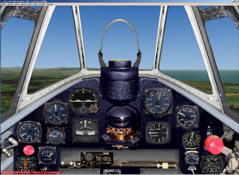
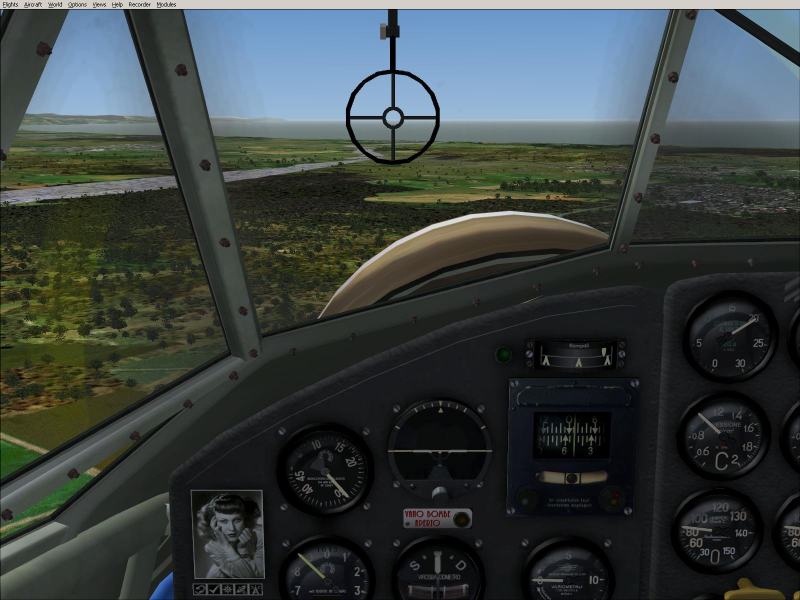
Original project CV with eyepoint and eyeline chosen by a photographer long ago
Cockpit views
often consist of a photograph over which bitmaps have been laid. A
photorealistic picture of a panel taken from a camera at a random eyepoint,
looking along a random eyeline, (in this case below the true pilot eyepoint and
eyeline), does not deliver a fully functional Cockpit View, even after
correction of scenery placement by deliberate
distortion of scenery perspective using the code
above. Before we have a functioning simulation control interface a 'views'
section must also be created.
[views]
view_forward_dir = 9
The DIR may
usually be allowed to default to zero yaw and roll correction. Yaw and roll
corrections are rarely required and are probably best avoided, consequently
view_forward_dir = 9, 0 , 0
is admissible
but the trailing zeroes are redundant
This
variable projects the 0.6 radians of external scenery, (scrolling
vertically in the rear window of the flight simulator and which in this case is
perspective squashed into only 5700 pixels), correctly versus the panel bitmap,
(static in the front window of the flight simulator), so that the elevation or
declination of every object in the scenery is realistic. When we use a flight
simulator we judge our flight path vector by comparing the position of the front
window, (with the 'panel' painted on it), to the scenery scrolling in the rear
window behind. From that parallax picture we judge our current flight path
vector , (including any glidepath), to anywhere in the scenery.
That parallax picture must be real not random.
True angle of elevation and declination from our eyepoint to the visible horizon, and to any scenery that we hope to reach or avoid, are vital in a flight simulator. They must never depend on where a photographer placed and pointed a camera lens long ago. The code, view_forward_dir= 9, corrects the scenery projection by replacing the eyeline down which the original camera lens was pointed during creation of the source image.
The [views] section and its vital view_forward_dir must never be omitted from an MSFS panel.cfg
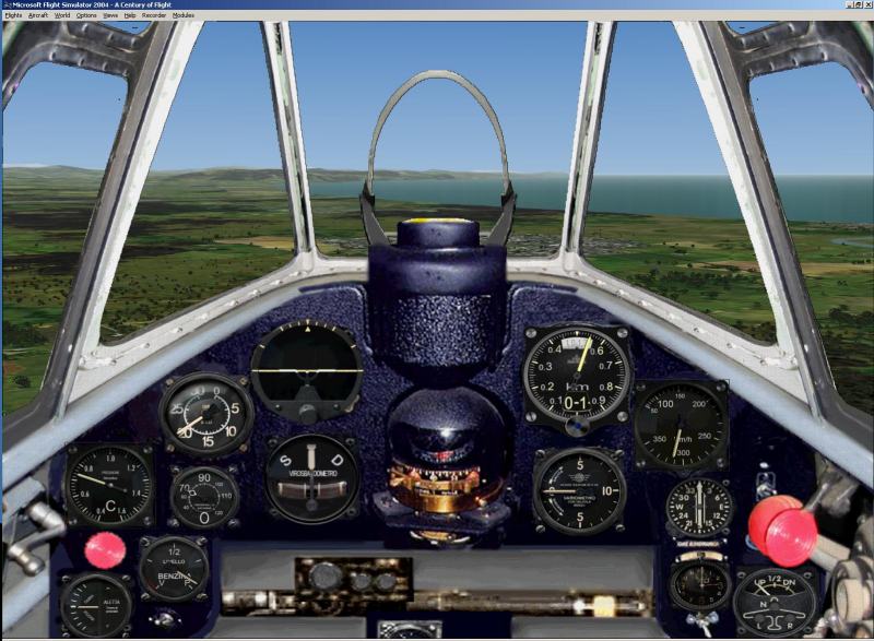
CV in level flight at zero pitch before harmonisation
(left) and after (right)
This tutorial
is not a gauge compatibility tutorial, but note in passing that many CFS gauges
are incompatible with FS9 and FSX. In this case the CFS default artificial
horizon in the original panel.cfg (left) displays zero pitch as positive pitch
and equal and opposite negative AoA. Gauges should never be selected because
they ‘look nice’. They must be selected after beta testing that they actually
work in the simulator that the project is said to be compatible with. The real
situation is shown on the FS9 compatible artificial horizon on the right. Note
that both pitch and VSI are zero.
The original flight simulation control interface (left) incorrectly displays the flight path vector as climb with the centre of the gunsight far above the horizon.
All of the
MC200 screenshots in this tutorial are just swaps of panel.cfg with no change in
the pitch (or anything else) being output by the constant flight dynamics which
was zero pitch in level flight throughout. The left hand screen shot illustrates
how a faulty simulation control interface projects the scenery with a false parallax relationship. We are misinformed by the
simulation interface that the aeroplane is nose up when it is not. The aeroplane
is in level flight and at zero pitch in both screen shots above. The original
user simulation control interface has a significant pitch display error
which must be corrected until the user interface correctly depicts what we
have achieved via our inputs, which in this case is the goal of level
flight at zero pitch.
‘Panel designers’ are required to project the flight simulator scenery correctly in both LAT/LON and relative pitch!
False flight path vector original (left) and real flight path vector after harmonisation
The ‘panel designer’ whose correct job title according to Microsoft is really 'Cockpit View designer' is responsible for coding the view from the cockpit, not just the view of the cockpit. It is his job to project all of the simulation scenery exactly where the gauges say the scenery should be, which is exactly where it is in real life. The gauges always use LAT/LON to point at scenery in azimuth and elevation (ADF only in azimuth, but ILS in both). In the example above we see that the FS9 compatible artificial horizon (right) is calculating correctly that the user has achieved zero pitch. The VSI shows that the user has also achieved level flight. Yet the original user simulation interface on the left projects (harmonises) the horizon randomly. Now notice that the significant pitch error in the original simulation control interface above not only confuses us concerning both aircraft pitch and aircraft flight path vector, but also prevents us from seeing where we are going! We cannot navigate by reference to the scenery even after achieving level flight at zero pitch. This design error must be corrected before that simulation control interface can be used in any flight simulator.
The post harmonisation screen shot has
prototypical gauges which also display the correct values, but they are not the
point of this tutorial. The parallax error has been removed using
VIEW_FORWARD_DIR. The simulation interface now indicates true pitch and true
flight path vector to the user. Those values were always being poked into
memory by the flight dynamics, but were being mangled by the broken simulation
control interface. The sea level horizon is now just below centre of the
gunsight in level flight at zero pitch. Visible curvature of the Earth is very
slight from this altitude (550 metres).
VIEW_FORWARD_DIR also controls user vertical Field of View (FoV) in Virtual Cockpit view.
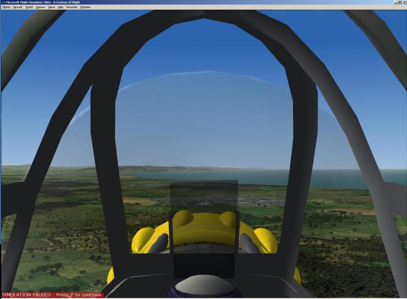
Original (left) has false eyepoint, parallax and
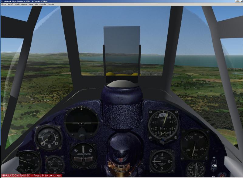
pilot vertical FoV – all corrected in harmonised VC right
After correction of the VC vertical Field of View (FoV) all the key gauges needed to control aircraft energy state become visible by default. Any other gauges which may be required are 'one click down' at default hat switch key repeat rates. The default FoV within the VC is controlled by the same mandatory View_Forward_Dir command above that controls scenery projection in Cockpit View. Because that single Microsoft variable controls two different things in two different simulation control interfaces the two interfaces must be harmonised at the design stage so that they project identical pitch parallax cues when flying head up, yet at the same time render all the key gauges visible by default in the project VC. The project design must simultaneously deliver a dual head up and head down picture in the VC so that an approach, (or combat), can be flown without any scrolling to see either the touchdown point or the necessary gauges. The default VC view should be neither wholly head up, nor wholly head down. The interface designer must use SIZE_Y in combination with VIEW_FORWARD_DIR to deliver the required harmonisation of the two user control interfaces.
The default VC view must deliver the
necessary head up and head down views simultaneously.
When the 2D
bitmap is perfectly designed, (as it should be for new projects if you are the
producer), it should be designed so that SIZE_Y = 6144 allowing the 0.6 radians
of vertically scrolling scenery in the rear window of the simulation to be
projected into 6K pixels with no perspective distortion. When we need
to harmonise a broken flight simulation control interface we do not have
that choice. We must determine the values of SIZE_Y and VIEW_FORWARD_DIR
that deliver all the goals above by trail and error. That may require
compromised and squashed scenery perspective as in this case; (SIZE_Y = 5700
needed v 6144 correct).
The approach must be flyable without resorting to video game cheat solutions to keep either the runway or the gauges in sight.
'Landing panels' and 'VFR panels' are never required.
That which is visible through the windscreen in real life, must be visible in our simulator and in both viewing modes.
VCs are not an excuse for denying users access to the head up view and the gauges simultaneously.
Flight simulators have scenery projection variables that must be encoded correctly until we see what the real pilot sees. He does not need to scroll and 'cheat' in real life and we should not be forced to scroll and 'cheat' when using flight simulators.
CV and VC harmonised for real
eyeline and parallax, but eyepoint in VC further forward and more realistic.
Vertical FoV in VC corrected.
The objective is not to place the horizon at the same position on the screen. The objective is to equalise the parallax between the front and rear windows.
How closely
the horizon position on screen matches just depends on the contour differences
of the two cockpit environments. The two simulation interfaces must be designed
so that the user derives the same pitch cue from both environments. The pitch
cue is a parallax cue. The two environments do not
have identical cockpit contours imposed on the front window of the simulation.
The scenery in the rear window of the simulation must be displayed by the
panel.cfg author to deliver identical parallax in the rear
window regardless. If anything the horizon might be positioned a little lower
versus the glazing bars at zero pitch in the harmonised VC with greater
discrepancy of horizon screen position between the CV and VC simulation control
interfaces. The correct solution never relates to equality of screen location.
The correct solution always relates to equality of parallax .
The types of gun sight which combat pilots look through, (there are other kinds in real life), are provided as precise parallax measuring devices. The guns are usually mounted parallel to the fuselage datum line in elevation. The bullets begin their flight parallel to that datum line and fall away with the ‘ballistic' trajectory caused by the gravity of planet Earth. The harmonisation point of the parallax gunsight intended to hit aerial targets at close range allows for very little bullet drop. To all intents and purposes it indicates the flight path vector when the aeroplane is in level flight and also at zero pitch.
If designing a user control interface for a combat simulator we would have no choice. We would be forced to equalise gunsight centre parallax precisely. When designing simulation control interfaces for a flight simulator we can and must take other parts of the airframe into consideration because the user of the simulation control interface will use the whole of the windscreen to frame the scenery and create the user parallax reference picture. That parallax picture is how the simulation interface conveys aircraft pitch. What it conveys must be real in both user interfaces. In other projects with greater variation of cockpit contour between the two viewing modes the position of the horizon on the monitor screen would need to differ much more to convey equality of parallax.
The screen shots in this tutorial all depict level flight with both zero pitch and zero bank which is the design time beta testing case. As users we also need to maintain level flight with bank applied whilst turning. We need to track the present or imagined parallax gunsight along the horizon whatever bank we apply. The simulation control interface must position the horizon correctly, not randomly else the user can never fly a head up level turn. Even when we intend to fly a climbing or descending turn we always need the cue for level flight to be real.
Unless the 2D bitmap is a screen grab of the VC from the VC eyepoint it will always be the least realistic simulation interface.
The 2D simulation interface is less realistic
Viewing the
screen shots above we can see that (even after harmonisation) the 2D interface
denies the simulation user the peripheral view of the ground ahead that the real
pilot has in level flight at zero pitch, (or any pitch, including especially
approach pitch, and tail down pitch on the ground). Flight simulation users need
to see the scenery to navigate in 4D, not the interior of the aeroplane. This is
particularly true of taildraggers during ground handling. The harmonised
VC above allows the simulation user sufficient peripheral vision to follow
taxiway and runway edges on the ground. Even when looking straight ahead the
peripheral vision is adequate for ground handling, especially keeping the
aircraft straight during take off
and landing on a runway with a defined edge, whether grass, dirt, or tarmac. The
2D bitmap does not provide that necessary user control interface.
Some of you
will have read that as a criticism of the original 2D bitmap. You misunderstood.
I am explaining the inherent deficiency of 2D panels (Cockpit View). The scale of
the CV bitmap could have been decided simply by taking the screen shot of the VC
above. However Kazunori Ito did not have that choice. The CV had to be designed
with sufficient vertical FoV to make the lowest and least used gauges of the
real panel visible by default. This forced him to move the CV eyepoint aft until
that required vertical FoV was on screen. This is not a design error, but
preferring that false aft eyepoint is a user error.
Flight simulation is all about navigating aeroplanes in 4D. For some or all of the flight we must navigate by visual reference to the scenery. Even after the parallax error in the original CV has been harmonised the requirement to have greater vertical FoV in CV forces the CV designer to obscure more of the scenery.
The CV designer has no choice he must hog the screen
obscuring scenery that should not be obscured and is not obscured in real
life
The designers
‘screen grab’ of the VC to create the CV, (or just scale the CV bitmap), must be
from an eyepoint further aft to deliver the extra FoV, in this case only extra
vertical FoV, but in many other aircraft also extra lateral FoV. We can see that
Kazunori Ito scaled the CV correctly. It has to be overscale. It has to block
sight lines it should not block to deliver adequate vertical gauge FoV. However
many 2D bitmaps are not produced to any scale at all. Many are wildly overscale
and hog the screen at the expense of the scenery which we need to see to
navigate in 4D.
The more scenery that is obscured, and the further aft the eyepoint is of the real eyepoint the less realistic the simulation. Flight simulation is about controlling parallax pictures. It is about aligning parts of the airframe with external moving or static scenery. The optimum choice if we want to understand what it was like to fly particular aeroplane x in real life is to use it with exactly the correct lines of sight blocked. In the combat case a fighter pilot often needs to ‘pull lead’ to have adequate angle off. It matters what ‘lead’ causes the target to disappear under the nose. As the harmonised MC200 VC discloses the real MC200 pilot can just see the tip of the nose from his real eyepoint. If the MC200 had a V-12 or a single row radial engine it would block more of the view. These things matter. The real eyepoint of the harmonised VC has more ‘scenery vertical FoV’ at the expense of ‘gauge vertical FoV’, but it is the VC with its realistic eyepoint that allows us to simulate MC200 operations realistically. That is true whether we are exploring difficulty of use in combat or the difficulty of flying the final approach. The penalty that we must pay for having the real world lines of sight from the VC is occasional one click hat switch snap scrolling to look at rarely used gauges below the default FoV of the VC.
The penalty for using
many VCs is huge because nobody bothered to design the default vertical FoV!
Far too many aircraft are uploaded with VCs in which the default FoV is just a liability to the user. VCs with FoV errors are almost as broken as CVs with parallax errors. They are functionally useless. The whole point of the VC is to block only the sight lines that are blocked in the real aeroplane from the real eyepoint. That does not preclude the design of VCs with FoVs that form superior simulation control interfaces to CVs. The CV will usually compromise our ability to see the mobile or static scenery that we may need to keep in view, whether it is an air to air target in a fighter, or a touchdown point in a propliner. CVs usually obscure parts of the scenery they should not obscure to have adequate vertical and/or lateral gauge FoV. Correctly designed VCs do not impose that liability.
Using a CV in a propliner, (or most other aircraft), compromises our ability to navigate en route by visual reference to the scenery, or to fly instrument approaches to the real world minima. The touchdown point will disappear under the nose before it should because the bitmap must be overscale and must obscure scenery it should not obscure to deliver the necessary gauge FoV. In VC we see what the real crew see and we can fly to the same minima. We can navigate en route and down the approach in lower visibility when using VC.
Using a VC is more realistic because it is always correctly scaled.
The fact that it is 3D is not a benefit. That is the price we pay to enjoy realistic simulation. Because a 3D environment is a price not a benefit it is essential that the VC FoV be correctly designed to minimise the price we all have to pay to to have the possibility of navigating in reduced visibility, seeing scenery that is blocked by the overscale CV. As visibility reduces the horizon is lower and lower in the sky. As visibility reduces the horizon tracks down our monitor screen.
At some visibility the overscale CV blocks all of the scenery and the 2D simulation control interface precludes simulation.
The VC is always to scale and does not block scenery that is not blocked in real life. In most cases only 3D simulation control interfaces can be correctly displayed to real world scale. Only they allow simulation to proceed in low visibility. 2D bitmaps should never be a pixel bigger than they need to be. They are always a liability to the user. They must be scaled so that the liability is minimised and they work as semi realistic flight simulation control interfaces obscuring nothing in the rear window of the simulation they do not need to obscure. The MC200 2D bitmap was scaled correctly and with great care by Kazunori Ito to minimise its liability, but these days do 2D bitmaps for single or tandem seaters serve any useful purpose?
Believe it or not flight simulators are about navigating aeroplanes. We need to see where we are going. We need to identify landmarks and line features from level flight. We need to be able to follow line features, (always slightly to our left), without scrolling to see them. We need to do that for hours in the cruise, and then we need to be able to see the airfield on the approach, and runway and taxiway edges on the ground. That is what a flight simulation control interface must deliver. A 2D panel must be more than randomly scaled artwork covering the scenery by which we need to navigate. Real pilots need to see where the aeroplane is going and so do we. Real pilots move their eyepoint until they can. That is what simulation control interface designers are supposed to do too. If they don’t we must, or the simulation control interface is useless.
The panel.cfg author must deliver the correct scenery location in the windscreen of both viewing modes simultaneously.
Projecting scenery correctly is not an optional extra when designing components for a flight simulator. The scenery projection code must be calculated and supplied by the author of the panel.cfg. He is responsible for harmonising what scenery appears where in the world outside in both viewing modes even if he is not the author of the VC. Panel design is potentially a minor part of Cockpit View design.
The ‘panel maker’ is the provider of both user simulation control interfaces. He is required to harmonise the visible content of the rear window in CV and user FoV in VC.
He is the member of the flight simulation community responsible for projecting all of the scenery at its real LAT/LON and at its real ‘angle off’. The majority of ‘panel makers’ are still unable to grasp this.
Original CV and VC
before harmonisation with huge variation of eyepoint and parallax. Both
parallax cues are false.
Neither the bullets nor the flight path vector are going where these original simulation interfaces pretend. In each case the aeroplane is in level flight and also at zero pitch. The bullets will not go into the sky and they won’t impact the rear of the cowling where the VC gunsight indicates they are aiming either. Just because we use a flight simulator rather than a combat flight simulator does not mean that we have no interest in where our flight path vector is going. The purpose of both of these simulation control interfaces is to show us where our flight path vector is going as a result of our skillful user inputs. For some reason flight simulation users worry endlessly about tiny errors in flight dynamics but fail to notice that the simulation control interfaces they use are causing huge errors that are not in the flight dynamics!
In level flight at zero pitch our
flight path vector and the bullets are really going here
Remember I am using these two fighter cockpit environments to illustrate a tutorial aimed at propliner users for three reasons.
1. They have no scaling errors and no graphics errors.
2. A project with 'gunsights' helps us to grasp the concept of 'harmonisation' of two views from two different eyepoints.
3. The different contours of the two front window interfaces demonstrates why the design requirement is to 'harmonise' scenery projection within those different front window contours in the two viewing modes. The front window of the 2D and 3D user simulation interfaces will often have different cockpit contours. The scenery in the window behind must be projected so that each contour in each interactive simulation interface delivers the same 'pitch parallax cue' from either interactive simulation interface.
The sea level
infinite visibility horizon must be just below our zero pitch eyeline from our
eyepoint (default view, no hat switch invoked up or down). The horizon will
always be just below (real or imagined) mid gunsight in level flight at zero
pitch. That is how we identify zero pitch in a flight simulator, because that is
how we identify zero pitch in a real aeroplane. We identify any other pitch by
noticing it is not zero, but first the pitch cue for zero must be correct! It
must be correct in both interactive user simulation interfaces. At zero pitch
the sea level horizon will be just below our default zero pitch eyeline,
(through any parallax gunsight, present or imagined), due to curvature of the
Earth. The higher we fly the more the earth horizon drops away from our zero
pitch eyeline, in real life or in MSFS. Consequently scenery projection code
must always be tested at zero pitch and low altitude by reference to the
horizon over the sea.
Every VC must deliver a default view that allows both head up and head down flight without user scrolling and without user cheats
The simulation control interface
must provide the necessary FoV
whilst delivering true parallax
Someone has to
'bother' to design this. It doesn't just happen! The someone who is supposed to
bother is the author of the panel.cfg. However if the creator of an entire
aircraft project has no intention of ever flying the aircraft, from the inside
looking out, because he just likes making model aeroplanes and only uses MSFS as
a radio control model aeroplane simulator, then someone else has to bother, and most of the
time that will have to be the downloader. Many / most 'panels' which claim
flight simulation compatibility deliver nothing of the kind for want
of a few lines of code. Remember during the enhanced realism harmonisation
process depicted here I did not alter one pixel of Kazunori Ito's bitmaps
or VC. They were not broken. I just bothered to calculate and write two lines of
very simple panel code correctly and I bothered to correct the eyepoint in the
original aircraft.cfg so that it now reads;
eyepoint=0.75, 0, 2.85
Bothering to calculate and write SIZE_Y=5700, view_forward_dir=9, and eyepoint= 0.75, 0, 2.85 is the difference between creating two flight simulation control interfaces that allow users to simulate the operation of an MC200, or bewildering them with random and different parallax cues which fail as user simulation control interfaces from either and both viewing modes, because they deliver false and differing flight path vector cues. There are other mathematical combinations of these three scenery projection variables that also project the scenery correctly and deliver the required vertical FoV in the VC, (because real pilots have different body sizes). What is required is that someone bothers to calculate and provide just one of those valid scenery projection solutions in every panel.cfg!
I cannot emphasise too strongly the extent to which users of flight simulators worry too much about realistic flight dynamics whilst flying with wholly random scenery placement and pitch parallax cues which are giving them false flight path vector cues. That makes no sense at all.
The MSFS scenery projection code, (just three variables), is much easier to calculate than realistic flight dynamics code.
Yet in many
uploads it is just randomised. There is endless babble in many forums about
‘fixing’ flight dynamics by users who cannot notice huge errors in the
simulation interface they are using to judge the flight dynamics!
There is no point in craving or creating realistic flight dynamics code for use with any aeroplane that has no functional simulation control interface capable of projecting the scenery correctly.
Nobody needs
realistic flight dynamics that pitch the aeroplane correctly to zero degrees, in
response to a given set of skillful user inputs, if that user does not care
whether the visual horizon is then displayed at minus 5 degrees or
plus 5 degrees when they use those skills and realistic dynamics to pitch
the aeroplane to zero degrees.
It matters whether the next ridge line is 5 degrees up or 5 degrees down when we are in level flight at zero pitch towards it!
It matters
whether the glideslope to a runway is displayed as three degrees or eight!
Displaying one as the other is not acceptable in any flight
simulator. Simulation control interfaces which display false flight
path vectors (including glidepaths) must be harmonised before use. We need
the real pitch parallax cue to display the real flight path vector being output
by realistic flight dynamics! There is much more to realistic flight simulation
than realistic flight dynamics. We need realistic simulation control interfaces. We
all need to be able to recognise how broken most of them are else we will not
understand the need to harmonise them ourselves, or discard them.
The user
simulation control
interface must show where the scenery really is whether we intend to
strafe it, bomb it or land on it!
Remember it is
the scenery that is being misprojected in all those screenshots. The 2D panel or
3D cockpit interior which are
the front window of the simulation never move a single pixel around the
screen.It is the scenery projection in the rear window of the
simulation that the panel.cfg author is required to calculate and encode
correctly, but that many never bother to encode at all! The angle down
to that scenery (declination = glidepath = flight path vector) must be real.
When the flight dynamics output a pitch of zero degrees our eyeline must be just
above the low altitude sea level horizon else all the other glidepaths and climb slopes are wrong by
the same amount. A real or imagined gunsight must have its centre just above
the sea level horizon, whether or not the simulator is a combat
simulator, whether we are using any CV or any VC.
When the
flight dynamics output a pitch of minus three degrees on final approach our
eyeline must be just above the touchdown point, not pointing at some random
location in scenery that was projected randomly by the panel.cfg
producer.
When we use a flight simulator we need to know where the aeroplane is going as a result of our inputs! Simulation interfaces that show it diving or climbing when it is in level flight at zero pitch are worse than useless. Users start developing stupid habits of aircraft operation or start tinkering with unbroken flight dynamics to correct huge simulation interface errors. Broken simulator control interfaces cannot be harmonised by flying with pitch errors or messing with flight dynamics. They must be corrected where the error was perpetrated by the designer of the simulation control interface. Cockpit environment design is all about projecting the simulation scenery correctly in the rear window of the simulation! That is why Microsoft call it a Cockpit View not a 'panel'.
When an
aircraft has no gunsight we must imagine one. In every 2D panel our eyeline must
be encoded to pass through the centre of the real or imaginary parallax gunsight
which is always directly in front of our eyepoint.
Our eyeline must be parallel to the fuselage (zero
pitch) datum line. When the aeroplane is in level flight at zero pitch the sea
level horizon must be just below that eyeline (due to curvature of the
Earth).
Before we can
use an aeroplane in a flight simulator we need a properly harmonised flight
simulation interface.
That is
created first by the correct mathematical harmonisation of SIZE_Y and
VIEW_DIR in the CV. The VC eyepoint variable is then harmonised with their
mathematical product to deliver the same result in VC. Making them the same is
not enough. They must both be real! The aeroplane must be going where the flight
simulation control interface depicts it as going.
Study the supplied screen shots below until you understand that the original MC200 VC eyepoint and eyeline are both false (too high) and that the horizon is in an impossible position versus the gunsight to depict level flight at zero pitch flight vector from the correct eyepoint. The pitch cue is correct, but from the wrong eyepoint.
Study the harmonised VC jpg to notice that the eyepoint is now realistic (behind the real or imagined parallax gunsight) and that the horizon parallax picture is real for zero pitch level flight at low altitude. Notice that the user vertical FoV has been corrected to create a functional flight simulation control interface which displays the real parallax picture AND all of the gauges needed to control energy state simultaneously. That is what any simulation control interface must deliver to the user by default.
The eyepoint variable and the VIEW_FORWARD_DIR variable in combination must deliver the necessary vertical Field of View that the real pilot adjusts his head and eyeline to achieve by default. The real pilot positions his head so he can see both where he (the aircraft flight path vector) is going and the gauges he needs to control aircraft energy state, whether in combat, or decelerating to Vref on approach.
Pilots need both the 'parallax reference picture' and simultaneous ability to see the energy state gauges.
One of those results is not enough. It is the job of the simulation control interface creator to deliver an eyepoint value and a VIEW_FORWARD_DIR value whose mathematical product deliver what the real pilot sees without requiring flight simulation users to employ silly video game cheats in either viewing mode.
Virtual Cockpits must
deliver the necessary vertical pilot Field of View else they are just a nuisance
to the user.
Remember in any project which has a CV we do not have freedom to vary VIEW_FORWARD_DIR at all. It must be encoded to deliver the true parallax picture which displays the flight path vector correctly in CV. The VC design goals above must be achieved by manipulation of eyepoint alone after determining the VIEW_FORWARD_DIR that creates true parallax and real scenery placement in the rear window of the simulation with CV in use. Errors in original camera lens eyepoint and eyeline of a photoreal bitmap, or a badly drafted 2D bitmap, may require SIZE_Y < 6144, but that should be avoided if possible. Simulation control interface design always begins with SIZE_Y = 6144 and we only compromise that value later and if absolutely necessary to achieve the stated design goals.
Savoia Marchetti S.M.79 VC with true eyepoint,
eyeline, vertical FoV and parallax at zero pitch
Now study the
screen shot of the Savoia S.M.79 VC above, originally by the 'Italian Wings'
team for CFS3, and subsequently adapted for use in MSFS, mostly by Manuele
Villa. Although it is a medium bomber P1 really had that gunsight. Notice that
the project eyepoint is correctly harmonised with the project
VIEW_FORWARD_DIR, and the project's
realistic flight dynamics. When the user skillfully achieves zero pitch in level
flight he can see that he has achieved his goal using the gunsight. Parallax is
harder to judge without a parallax sight, but the flight path vector displayed
to the user would be (and must be) real anyway. Notice that when aeroplanes are
in level flight and also at zero pitch those who fly them can see where they are
going! That is in fact the point of flight simulation. Flight simulation is the
skill of compliant aircraft navigation in 4D in all weathers. No one
can acquire or retain that real world skill using flight simulation control
interfaces with randomly projected scenery!
Using broken flight simulation control interfaces may constitute a flight safety hazard for real aircrew.
The parallax picture must be as realistic as the flight dynamics. The flight simulation files must be properly harmonised. No video game cheats should be required to see where the flight path vector is taking the aeroplane, whilst simultaneously having access to all the required energy state gauges.
The energy state gauges include AH, ASI and VSI as well as MAP and RPM.
The S.M.79 screenshot shows pretty much the real panel layout in the real cockpit space, from the real eyepoint. There is no 'cheating' by the producers and they imposed no requirement for silly video game cheating by the downloader. The eyepoint is just far enough aft to include the slip ball within the vertical default FoV. When zero VSI is mandated no scrolling is required to cross check the head up picture with the head down picture. If you focus your eyes on the horizon the gauges will be out of focus, but just like real life they are just a pilot eye movement below. Please practice doing that now.
That change of eye focus does not require a head movement in real life and it does not require scrolling in FS9.
Always provided somebody bothered to design the user
simulation control interface properly.
Things that would be out of focus in real life without a head movement are not visible by default. They are one hat switch click down or right. Those who prefer not to (snap) pan and (snap) scroll can use the icons bottom left to pop up things that are not in view by default. When designing or fixing the VC FoV we must consider the difference between eye movement and head movement. However we must always remember that the further back in aviation history we go the worse the ergonomic design of the real cockpit environment is likely to have been. Replicating the difficult working environement in many real historic cockpits is not always a design error. It is however always a choice. Gauge positions can be swapped. or moved a little, or gauge diameters can be reduced, to deliver an easier to use simulation control interface with adequate FoV. Like everything else in this tutorial that requires nothing more than Windows Notepad to (re)design.
Now study
where the real parallax gunsight is in the real S.M.79 windscreen versus the top
of the real panel. That position is real world; not a position faked by the
producers to deliver the goals specified in this tutorial. Now use that screen
shot to inform your understanding of where the virtual gunsight, (the real pilot
eyeline), is in real life in a real 'propliner' or other large side by side seat aircraft
when the crew sit in a cockpit near the nose of the aeroplane. Notice
that pilots who sit 'up front' can see more of the scenery than fighter
pilots who sit at CoG to minimise ear canal disturbance. In a
'propliner' with no engine in the nose all of the scenery above the panel
would be visible in level flight at zero pitch. Navigation by visual
reference to the scenery is possible down to very low visibility minima
when aircrew sit 'up front'.
The key is to
notice where the (real) eyeline is in the vertical depth of displayed windscreen
in front of the (real) eyepoint.
Notice the realistic peripheral vision which allows P1 to follow a taxiway edge or runway edge even whilst looking straight ahead. Having the real peripheral vision makes it easy for us to follow line features and height keep in low visibility too. The freeware Savoia Marchetti S.M.79 can be downloaded from the usual websites should you wish to examine how easy it is to operate a large aircraft from a correctly designed VC, in which you can see the gauges you need to see head down, and the parallax picture you need to fly head up simultaneously. It is even easy to just slide from the P1 to P2 seats without losing situational awareness in a correctly designed FS9 VC. Both should work equally well. The Macchi M.C.200 enhanced realism update was still a work in progress at the time this tutorial was published. It will be available for study at a later date.
Most 'panel makers' and 'VC creators' have no adequate aviation background. We cannot expect them to understand what they are supposed to be doing, or to explain what they are supposed to be doing to one another. The whole idea that they are supposed to be creating the flight simulation control interface and that they are required to project the scenery at its real LAT/LON, and with the real glidepath is wholly lost on most of them.
Perhaps if all the
moderators of 'panel design forums' renamed them 'simulation control interface
design forums' those involved in creating them might understand their role in
the flight simulation community better?
Many aircraft releases and many 'stand alone' panel releases continue to contain no functional user simulation control interface. The vital parallax relationship between the front window of the simulation and the rear window is all too often false and randomly false in the Cockpit View. It tells us that our flight path vector is one thing when it something quite different. Many VCs continue to be produced with a random FoV from a random eyepoint making them no more than a nuisance to use.
The role of
simulation interface designers is identical whether the simulation control
interface they are designing is for a combat simulator or a flight simulator.
Their role is to deliver true parallax between any front window (panel contours)
that they design and the scenery in the rear window whose
content they are also required to design . Their role is to carefully
position and reveal the scenery for navigation !
Study this
text and screenshots until you understand how to recognise broken simulation
control interfaces and how to harmonise them. The best way to learn is to
practice manipulation of the three allowable MS variables that every cockpit
designer must use to place the simulation scenery correctly. Remember many
flight simulation interfaces are so badly designed that they may have no [Views]
section at all. You may need to create one.
Before all
those broken simulation interfaces can be used for flight simulation we
must harmonise them, else we must discard them.
SUMMARY
1) In every 2D panel our eyeline must be encoded to pass through the middle of the real or imagined gunsight in front of our eyepoint. Our eyeline must be parallel to the fuselage (zero pitch) datum line. When the aeroplane is in level flight and also at zero pitch the sea level horizon must be just below that eyeline (due to curvature of the Earth).
2) The VC
eyepoint must then be encoded to deliver the identical parallax reference
picture when user eyepoint is switched, (with the simulation paused and by
cycling the S key), displaying identical flight path vectors to everything in
the scenery. That can also be achieved simply by using the same 'gunsight v sea
level horizon harmonisation technique', whether or not the real aircraft
actually has a parallax gunsight.
3) Default vertical FoV in VC is also controlled via VIEW_FORWARD_DIR. This must first be used to create the real parallax picture in CV above. However different combinations of SIZE_Y and VIEW_FORWARD_DIR can all deliver the real parallax in CV. The one needed from the many possible is the one that delivers the required vertical FoV in VC at the highest possible value of SIZE_Y (not exceeding 6K = 6144 pixels) which is parallax compliant in CV. Always attempt to create CVs which are functional with SIZE_Y=6144 before imposing a lower value that distorts scenery perspective.
All these problems can be greatly minimised by the creation of VC only releases and those who need to harmonise and create a functional FoV for a broken VC will find that much easier if they are willing to discard the CV. Once an aircraft has no CV the VIEW_FORWARD_DIR variable is not used by FS9.exe in the scenery projection parallax equation and may be used solely to create the necessary VC vertical FoV. This can easily reduce the effort required to create a functional user simulation control interface by 90%. When a CV is correctly designed it is hardly less useful than a correctly designed VC, but it adds a huge burden to the simulation interface design workload. Always consider whether you need a CV before you do the work to create one or harmonise one that is broken.
All of the
above is true for both FS9 and FSX.
ZOOM
ISSUES
See addendum at bottom if you use a wide screen monitor.
Panel.cfgs for use in FS9 must be
free from random ZOOM statements.
Random ZOOM statements inserted into FS9 causes false scenery placement that cannot be corrected by any means. The Microsoft FS9.exe code must be allowed to impose the correct value in every direction.
Flying with a false ZOOM to misplace the scenery at false LAT/LON is the silliest mistake any flight simulation user can make.
The 2008 Propliner Tutorial explains why (see below). The design goals above cannot be met by imposing false scenery placement with false ZOOM values to cover up bad simulation interface design.
Imposing fake zoom factors just compounds the simulation interface design error by adding false LAT/LON to false parallax cues.
FSX has additional and serious design errors by default. FSX is different with regard to ZOOM. Consequently FSX has its own scenery harmonisation tutorial by Tom Gibson which is linked from the same page as this tutorial.
FSX requires ALL the corrections above and ALL the additional corrections in the FSX simulation interface tutorial by Tom Gibson.
The design
errors in FSX are explained and illustrated in greater detail within Part 2A and
Part 7 of the 2008 Propliner Tutorial also available from ;
Stop reading
now. Go and practice identifying broken simulation interfaces by flying or
slewing cockpit environments to zero degrees pitch at low altitude over the sea.
Did the creator deliver real parallax to deliver the real flight path vector in both viewing modes?
Did the creator deliver realistic FOV in the VC?
If not practice manipulating the three allowable scenery projection variables, (VIEW_FORWARD_DIR + SIZE_Y + eyepoint), but never ZOOM to deliver real parallax, then refine that skill to allow the required vertical FoV in VC mode without invoking false parallax and false scenery placement in either viewing mode. Remember false parallax is the same thing as displaying false flight path vectors and a simulation control interface which displays false flight path vectors is worse than useless however pretty it may be.
FSAviator 4/2008
The tutorial above was written for older "square" monitors (4:3 proportion), or if you use a wider monitor you fly FS in a window and make that window the same 4:3 proportion.
If you use a widescreen monitor and instead the outside view stretches all the way across the monitor, to maintain the same outside view you will need to change the zoom value.
As an example, I use a 1920 x 1080 monitor. This has a 1920/1080 = 1.778 proportion, compared to a square screen's 4/3 = 1.333 proportion. Since FS changes the apparent zoom as you widen the outside view, we have to compensate by changing the zoom value the opposite way. The proper amount to change the zoom is the ratio of the "normal" square screen proportion to your monitor's proportion. For me this means 1.333 / 1.778, or 0.75. Since the proper zoom value using a square screen in FS9 is always 1.0, I now need to use a zoom value of 0.75 so my widescreen monitor displays the same apparent zoom as the square monitor did.
If your monitor has a different screen proportion, just substitute those values into what I did above and get your own zoom values. For example, "16:10" screens need a zoom value of 0.85 in FS2004.
In FSX you can eliminate this problem by using a cfg file setting. Please see the FSX Propliner Tutorial for details.
Tom Gibson