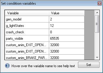
| Variable | Value | Notes |
| gen_model | 2 | Loads the external model. If you are converting the VC, set this to 1 |
| g_lightStates | 12 | retains the attachpoints for the landing and taxi lights for the external model, if loading the VC set this to 0 |
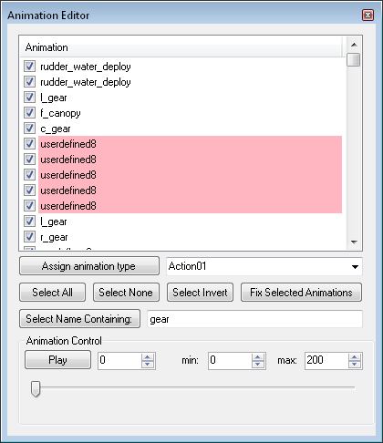
| c_gear | 100 | allows the wheels to display |
| l_gear | 100 | " |
| r_gear | 100 | " |
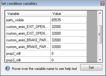
| parts_visible | 65535 |